kicad-developers team mailing list archive
-
 kicad-developers team
-
Mailing list archive
-
Message #39421
Re: Version 6 development planning
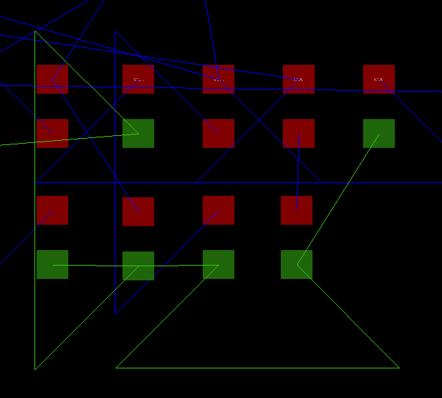
As nothing more than an example, here is another tool facing the same
issue. I've colored one net's ratsnest green (others are still blue) and
you can see pins at orthogonal locations to each other get a zig (or is
that a zag?) so the individual pins on the net can still be easily
identified.
[image: image.png]
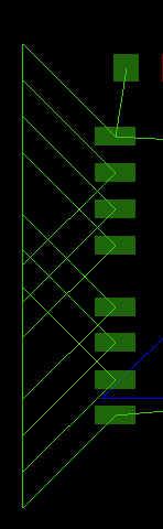
It does look a little wacky if there are many pins on the net close
together so the zig can't complete before hitting into the next zig:
[image: image.png]
But once over that minor hurdle of understanding what you're seeing the
first time, this is clear.
On Wed, Feb 13, 2019 at 6:32 AM John Beard <john.j.beard@xxxxxxxxx> wrote:
> On Wed, Feb 13, 2019 at 2:28 PM Jeff Young <jeff@xxxxxxxxx> wrote:
> >
> > >> I'm also not
> > >> completely sure curved air wires will be necessary once we implement
> the
> > >> coloring feature.
> >
> > I wonder if this is a digital vs. discrete thing? With transistors in
> particular, I often find several ratsnest lines going directly over the 3
> pins, and having no idea which one connects to which.
>
> Also when you have an ICs or headers with multiple GND pins in the
> same row, it looks like all the pins between them are connected
> together. I don't think colouring will really help having
> "co-incident" lines on top of each other. I feel the two are
> complementary features.
>
> Cheers,
>
> John
>
> _______________________________________________
> Mailing list: https://launchpad.net/~kicad-developers
> Post to : kicad-developers@xxxxxxxxxxxxxxxxxxx
> Unsubscribe : https://launchpad.net/~kicad-developers
> More help : https://help.launchpad.net/ListHelp
>
Follow ups
References
-
Version 6 development planning
From: John Beard, 2019-02-09
-
Re: Version 6 development planning
From: Jon Evans, 2019-02-09
-
Re: Version 6 development planning
From: Wayne Stambaugh, 2019-02-09
-
Re: Version 6 development planning
From: Wayne Stambaugh, 2019-02-09
-
Re: Version 6 development planning
From: Jeff Young, 2019-02-11
-
Re: Version 6 development planning
From: Wayne Stambaugh, 2019-02-12
-
Re: Version 6 development planning
From: Brian Piccioni, 2019-02-12
-
Re: Version 6 development planning
From: Wayne Stambaugh, 2019-02-13
-
Re: Version 6 development planning
From: Jeff Young, 2019-02-13
-
Re: Version 6 development planning
From: John Beard, 2019-02-13