kicad-lib-committers team mailing list archive
-
 kicad-lib-committers team
-
Mailing list archive
-
Message #00154
Silk screens over pads and naming
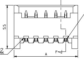
I'm working on the THT Right-Angle Molex Picoblade headers. I have a
question about the silk screen.

If you look at the datasheet, the line of the body intersects the pins
along the back edge. What should I do about the silkscreen in this case?
Artificially extend it away from the pads (in which case the SS won't
look like the body), break the line over pads (in which case a SS-only
view would be full of disjoint lines), or do what I did for now and run
the line over the pads. The latter has never caused me a problem before:
most of <well-known proprietary PCB software often used by hobbyists>
modules do this.

Another question is what should I do with the names? The convention
document isn't that clear about connectors. Currently, they look like

  MOLEX_53398-0271_2PIN_SMD_VERT.kicad_mod

I am planning to change to:

  Molex_PicoBlade_53398-0271_2Pin_SMD_Vert.kicad_mod

I think it is useful to have the range name in there, as opposed to just
the part numbers, to make it easier to find in the list (then
PicoBlade modules sort together, as do MicroFit and so on). The part
numbers are not sequential in the range: we have 53047, 53048, 53261
and 53398. It's a bit longer, however.

Does anyone have any opinions on these points?

Thanks,

John
Attachment:
Molex PicoBlade RA example.png
Description: PNG image
Follow ups